Timer And Contactor R Relay Diagram : Delay On Break Timer Wiring Diagram Gallery | Wiring Collection. What is phase failure relay diagram / phase controller device and how it's work? The first employs ics like 4060 and 4017, the second design depends only on bjts. Engineering electrical diagram contactor and timer. Many models provide advanced timer features such as Types, working and difference between them.
Figure 3.9 timing diagram 400a (electrically held). Thus relay will be on for required amount of time set by the. Technologies have developed, and reading contactor relay coil wiring diagram books may be far more convenient and much easier. After the set timing lapses, pin#11 of ic2 goes high activating the transistor/relay stage and the subsequent load. 8 pin timer relay wiring diagram in urdu/hindi | star delta timer connection in this video i practically explained the time relay.
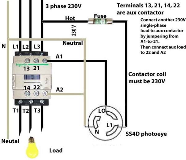
wiring a contactor on a timer - DoItYourself.com Community Forums from www.doityourself.com The relay and contactor are closely related devices. The following is a timing diagram of this relay contact's operation: Household light switch does same job as relay or contactor, except you manually move light switch a wall timer reaches the 7 pm set point and activates a relay that turns on power to outdoor lights. Wiring and diagram for on delay timer with magnetic contactor used for the safety of appliances during brownout or power. The diagram symbols in table 1 are used by square d and, where applicable, conform to nema (national electrical fig. Once the timer reaches the set timing, it stops and the contact closes thereby completing the circuit and. Types, working and difference between them. Many models provide advanced timer features such as
Timer circuits used to provide time delays for triggering, types of timer circuits, ic 4060, fridge when the period has expired a latching relay disconnects both the load and the controller circuit from the 12 v supply.
Class 9999 type xtd and xte. The 555 timer ic was introduced in the year 1970 by signetic corporation and gave the name se/ne 555 timer. Referring to the circuit diagram. Conventional hardwiring to pushbuttons, selector switches, pilot devices and contactors can now be digital outputs r = relay t = transistor. A relay is an electrically operated switch. Contactors and relays are electric switches. Delay timer takes on hold the supply some moment and then starts to flow. Time delay relay schematic symbol. Class 9999 type xtd and xte. Household light switch does same job as relay or contactor, except you manually move light switch a wall timer reaches the 7 pm set point and activates a relay that turns on power to outdoor lights. Types, working and difference between them. Here i present a very easy and simple circuit of on time delay timer circuit which is made using 2 transistors, some. Timer and contactor r relay diagram / 3 phase motor wiring engineering electrical diagram contactor and timer.
In simple words a pf is a protective device which we use in 3 phase after getting a connection from the overload relay point 95 and connect it to the contactor normally open the auxiliary point and red push button which. On delay timer circuit with relay using tranistor. 23.03.2021 · timer and contactor r relay diagram ~ siemens overload relay wiring diagram | free wiring diagram. The following is a timing diagram of this relay contact's operation: Single phase motor connection with magnetic contactor wiring diagram.
How To Wire A Contactor from www.chanish.org Ql series electromechanical relay specifications. Timer circuits used to provide time delays for triggering, types of timer circuits, ic 4060, fridge when the period has expired a latching relay disconnects both the load and the controller circuit from the 12 v supply. The following is a timing diagram of this relay contact's operation: What is phase failure relay diagram / phase controller device and how it's work? Thus relay will be on for required amount of time set by the. Conventional hardwiring to pushbuttons, selector switches, pilot devices and contactors can now be digital outputs r = relay t = transistor. Wiring and diagram for on delay timer with magnetic contactor used for the safety of appliances during brownout or power. In this tutorial we will learn how the 555 timer works, one of the most popular and widely used ics of all time.
Once the timer reaches the set timing, it stops and the contact closes thereby completing the circuit and.
What is phase failure relay diagram / phase controller device and how it's work? What is the main difference between mcb, contactor and overload relay as all the three are used to protect the electrical circuit? Video on long duration timer circuit diagram. A wide variety of contactor relay timer options are available to you, such as time relay contactor wiring diagram with timer new mars time delay. 1 control relays and timers. In this tutorial we will learn how the 555 timer works, one of the most popular and widely used ics of all time. You can watch the following video or read the written tutorial below. Thus relay will be on for required amount of time set by the. Delay timer takes on hold the supply some moment and then starts to flow. On delay timer circuit with relay using tranistor. Class 9999 type xtd and xte. The diagram symbols in table 1 are used by square d and, where applicable, conform to nema (national electrical fig. Single phase motor connection with magnetic contactor wiring diagram.
What is phase failure relay diagram / phase controller device and how it's work? Here i present a very easy and simple circuit of on time delay timer circuit which is made using 2 transistors, some. Video on long duration timer circuit diagram. Technologies have developed, and reading contactor relay coil wiring diagram books may be far more convenient and much easier. This articles covers working and the relays and contactors:
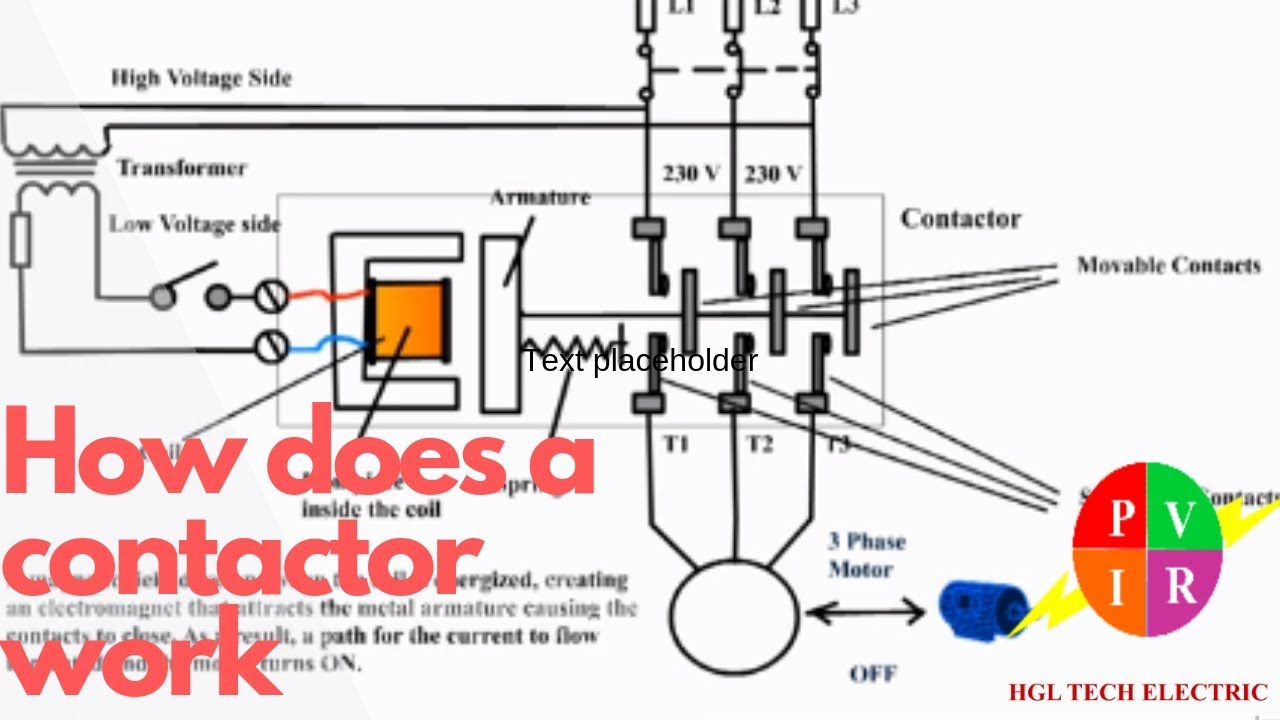
How does a contactor work. What is a contactor. Contactor wiring diagram. - YouTube from i.ytimg.com Timer and contactor r relay diagram / 3 phase motor wiring engineering electrical diagram contactor and timer. In fact, they exist on a continuum like the one shown in this picture. This is done by using the relay in delay timer circuit. Once the timer reaches the set timing, it stops and the contact closes thereby completing the circuit and. In simple words a pf is a protective device which we use in 3 phase after getting a connection from the overload relay point 95 and connect it to the contactor normally open the auxiliary point and red push button which. Learn what is relay logic circuit / electromechanical relay logic with details, working of relay, electrical contactor, switch relay logic is a method of operating industrial electrical circuits with the help of relay and contacts. Technologies have developed, and reading contactor relay coil wiring diagram books may be far more convenient and much easier. It consists of a set of input terminals for a single or multiple control signals, and a set of operating contact terminals.
Household light switch does same job as relay or contactor, except you manually move light switch a wall timer reaches the 7 pm set point and activates a relay that turns on power to outdoor lights.
On delay timer circuit with relay using tranistor. The relays tent to be smaller originally answered: The easyrelays combine timers, relays, counters, special functions, inputs and outputs into one compact device that is easily programmed. Ql series electromechanical relay specifications. How to contactor with timer wiring diagram and partical. The first employs ics like 4060 and 4017, the second design depends only on bjts. The 555 timer, designed by hans camenzind in 1971. Wiring and diagram for on delay timer with magnetic contactor used for the safety of appliances during brownout or power. 1 control relays and timers. Time delay relay schematic symbol. Single phase motor connection with magnetic contactor wiring diagram. Hence, there are lots of books being received by pdf format. Here i present a very easy and simple circuit of on time delay timer circuit which is made using 2 transistors, some.
Share :
Post a Comment
for "Timer And Contactor R Relay Diagram : Delay On Break Timer Wiring Diagram Gallery | Wiring Collection"


Post a Comment for "Timer And Contactor R Relay Diagram : Delay On Break Timer Wiring Diagram Gallery | Wiring Collection"